IEEE 1588-2008 also known as Precision Time Protocol (PTP) v2, is a two-way packet-based communications protocol designed to precisely synchronize clocks to sub-microsecond accuracy. The PTP standard incorporates hierarchical master-slave architecture for clock distribution. Under this architecture an ordinary clock is a device with a single network interface and is either a master or a slave. A boundary clock (BC) is a device with multiple network interfaces. One of them acts as the slave clock and the other acts as the master. A Transparent clock (TC) is a device that measures the time taken for PTP message to transit the device and provides this information to clocks receiving this PTP message.
The root timing source is called the grandmaster. The grandmaster is the prime master which transmits synchronization information to the other devices on the network. The synchronization information is timestamp carried by PTP UDP or Ethernet packets. The protocol defines events and general PTP messages. Event messages are messages with timestamp. An accurate timestamp is generated at both transmission and receipt. General messages do not require accurate timestamps. The PTP event messages are: Sync, Delay Req, PDelay Req and PDelay Resp. The PTP general messages are: Follow Up, Delay Resp, PDelay Resp Follow Up, Announce, Management and Signaling.
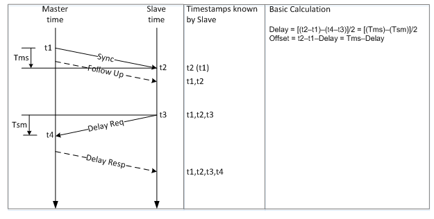
A typical PTP packet exchange is shown in the figure below.

The master sends a PTP packet called Sync message which includes a timestamp known as t1, and an optional Follow Up message, in case of the two steps operation, which includes the Sync t1. The slave receives the Sync/Follow Up message, keeps its timestamp and the Sync message arrival time, known as t2, and sends a Delay Request message back to the master. The Delay Request message does not include a timestamp, however the slave keeps the time it sent the Delay Request message, known as t3. The master receives the Delay Request message and keeps its arrival time known as t4. The master then sends back a Delay Response message. The Delay Response message includes t4. At the end of the messages exchange, the slave has four timestamps:t1, t2, t3 and t4. From those four timestamps, assuming an ideal network is used, the slave can calculate the network delay and adjust its clock.
The mathematical assumption of the PTP network delay calculation is that the upstream and downstream paths’ delays between the grandmaster/master clock and slave clock/boundary clock are equal. The path delay is comprised of three types of delay elements: link delay, serialization delay, and packet delay variation (PDV). Link delay and serialization delay are static and potentially asymmetrical components. The PDV embodies the actual variation in packet delay propagation as packets pass through switches and routers. Typical Ethernet switch/router has input and output buffers communicating over a very high-speed back plane or switch fabric. The major contribution of PDV arises from the output buffering and queuing. If the output subnet is always available for accepting packets, the delay fluctuation will be low. Intensive traffic may cause increased delay fluctuation due to this output buffering. This PDV is the primary cause of IEEE 1588 time errors.
The boundary clock and transparent clock can reduce the network PDV and thus improve the clock synchronization accuracy. The boundary clock typically has several physical ports corresponding with each physical port communicating with the network. The messages related to synchronization, establishing the master-slave hierarchy, terminate in the protocol engine of a boundary clock and are not forwarded. Two versions of the transparent clock were defined: end-to-end and peer-to-peer. The end-to-end transparent clock forwards all messages, just as a normal switch or router does. However, for PTP event messages, the residence time measures the amount of time it takes for a packet to traverse the switch or router. These residence times are accumulated in a special field, the correction field. This correction is based on the difference in the timestamp generated when the event message enters and leaves the transparent clock. The peer-to-peer transparent clock is a transparent clock that in addition to providing PTP event transit time information, it also provides corrections for the propagation delay of the link connected to the port receiving the PTP event message. When the IEEE 1588 packet arrives at its targeted slave clock or boundary clock, the IEEE 1588 protocol extracts the contents of the correction field and subtracts its value from the computed delay. The expected result of this process is a dramatic reduction in PDV, improving the clock synchronization accuracy.
Typical PTP device is composed of 3 elements: servo, protocol stack and hardware assist functions. The clock servo is used to adjust the frequency and time of the slave or BC clock. The ultimate goal is to match the frequency and time of the slave or BC clock with that of the master clock, in order to maintain zero offset between the two clocks.
The overall synchronization accuracy is a function of several elements: servo performance, oscillator quality, PDV and delay asymmetry. Excluding the delay asymmetry that cannot be handled by the PTP end device, the major challenge of the PTP device is to deliver high and robust synchronization performance with the presence of significant PDV while using a low cost oscillator. IPClock’s servo leverages IPClock’s innovative clock recovery technology to provide exceptional immunity to packet switched network impairments. IPClock’s products enable significant cost reduction without compromising on clock synchronization accuracy, taking advantage of IPClock’s support of low cost oscillators. IPClock’s devices deliver timing accuracy better than ±1µsec and frequency accuracy better than 16ppb on a none-PTP aware 10-switch GbE network under ITU-T G.8261 conditions.
